|
BALANCING OF
ROTATING EQUIPMENT COMPONENTS
|
To give an
overall idea about the balancing of Rotating Equipment components to the
Maintenance and Operations personnel.
Scope:
The scope of the manual is
to explain the purpose of balancing the rotating equipment components and to
give a brief information about the balancing procedures, balancing machines and
the prevalent balancing standards.
Terminology
1.1 Balance Quality Grade: G Xxx
1.2 Center Of Gravity
1.3 Principal Inertia Axis
1.4
Correction Plane (For Balancing)
1.5 Static Unbalance
1.6 Couple Unbalance
1.7 Critical Speed
1.8 Dynamic Unbalance
1.9 Rotor
1.10 Rigid Rotor
1.11 Flexible Rotor
1.12 Specific Unbalance
1.13 Residual
Unbalance
1.14 Permissible Residual Unbalance (U per
)
1.15 Units Of Unbalance Introduction
2.1 Reasons For Balancing
2.2 Causes Of Unbalance
3 Safety & Environmental Precautions
3.1 Safety Of The Balancing Machines
3.2 Safety While Balancing The Rotors
3.3 Safety
During The Field Balancing Of The
Rotating Equipment :
4 BALANCING
MACHINES:
4.1 Gravity Balancing Machines:
4.2 Centrifugal Balancing Machines:
4.2.1 SOFT BEARING
BALANCING MACHINES
4.2.2 HARD BEARING
BALANCING MACHINES :
5 BALANCING METHODS
5.1 Preparation For Balancing
5.2 Shop Balancing
5.2.1 SYMMETRICAL ROTOR
5.2.2 SYMMETRICAL ROTOR
WITH OUTBOARD BALANCING PLANES –
5.2.3 OVERHUNG AND NARROW
ROTORS
5.3 High Speed Balancing –
5.4 Field Balancing-
6 BALANCING STANDARDS.
References
1 Terminology
1.1 Balance Quality Grade: G Xxx
For rigid rotors, G , is the product of specific unbalance , e, and rotor maximum service
angular velocity. Service angular velocity is nothing but the service RPM
expressed in radians per second.( w )
G = e * w
1.2 Center Of Gravity –
The point in a body of a rotor through which the
resultant of the weights of its component particles passes for all orientations
of the body with respect to a gravitational field is called the center of
gravity - C.G.
This can also be described as the point about which
the rotor’s weight is equally distributed.
1.3 Principal Inertia Axis –
A line about which the rotor weight is equally
distributed is known as Principle Inertia Axis ( PIA in short ) . It is obvious
that the Center of Gravity ( CG ) is
always on the Principal Inertia Axis ( PIA )
1.4 Correction Plane (For Balancing)-
The plane perpendicular to the shaft axis of a rotor
in which correction for unbalance is made. The correction can be in the form of
material addition, or material removal, or any change in the weight
distribution in this plane.
1.5 Static Unbalance
It is that condition of unbalance for which the central
principal axis is displaced only
parallel to the shaft axis.

1.6 Couple Unbalance
It is that condition of the unbalance for which the
central principal axis intersects
the shaft axis at the center of gravity.

1.7 Critical Speed
It is that speed at which a system resonance is
excited. The resonance may be of journal supports ( rigid mode ) or flexure of
the rotor ( flexural mode ). There are many critical speeds for a rotor and
they are denoted like first, second, third in lateral and torsional modes.
1.8 Dynamic Unbalance
It is that condition of unbalance for which the
central principal axis ( PIA ) is not
parallel to and does not intersect the shaft axis. Obviously the CG is
not on the shaft axis as well .It is usually a combination of the static and
couple unbalance. This is the type of unbalance, which is usually found in
practice in the unbalanced rotor.

The Dynamic unbalance is
equivalent to two unbalance vectors in two specified planes, which completely
represent the total unbalance of the rotor.
Dynamic unbalance may also be
resolved into a static and couple unbalance vectors whose vector sum is also
equal to the total unbalance of the rotor.
1.9 Rotor
A body capable of rotation, which generally has journals
supported by the bearings.

1.10 Rigid Rotor
A rotor is considered rigid if its unbalance can
corrected in any two correction planes. After the correction, the residual
unbalance does not change significantly at any speed up to the maximum service
speed. In other words it also means that the rotor service speed is much lower
than its first lateral critical speed.
1.11 Flexible Rotor
A rotor that does not satisfy the definition of the
rigid rotor is known as a flexible rotor. It also means that the rotor needs to
be balanced in such a way that it remains reasonably balanced while it attains
the maximum service speed. The rotor of this class runs at least above the
first lateral critical speed. While passing through the critical speeds there
is some amount of elastic deflection depending on the mode shapes. The
correction planes are so selected that, the elastic deflection has no severe
impact on the balance of the rotor, at that speed range.
1.12 Specific Unbalance
The static unbalance U divided by the rotor mass M.
This will also yield the value for mass eccentricity, which is denoted by “ e “
1.13 Residual Unbalance
The unbalance of any kind that remains after the
balancing of the rotor is known as residual unbalance. This must be less than
the permissible value, as per the balancing standers adopted for that class of
rotor.
1.14 Permissible Residual Unbalance (U per )
The maximum residual unbalance permitted for a rotor
or for a correction plane for the rotor is termed as permissible residual
unbalance. This is expressed as
U per = e per x m , Where m is
the mass of the rotor.
1.15 Units Of Unbalance
Unbalance is measured in
gram-millimeters or ounce inches. It simply means the quantity of unbalance
mass (m) , multiplied by the distance (
R ) from shaft axis.
As an example, an unbalance of 15
gm at 100 mm radius will introduce an
unbalance of ( 15 x 100 ) = 1500 gm-mm ,
in that plane.
This is independent of speed of
rotation. However the same unbalance will produce higher centrifugal force if
the speed of rotation increases. In fact the centrifugal force generated due to
unbalance is proportional to the “ square “ of RPM. ( F =
m x R x W x W)
2 Introduction
One of the basic problems in
the rotating machinery is the unwanted vibration. Since the rotor rotates, if
it is out of balance, vibration will be present primarily because of the
unbalance. This can corrected by balancing the rotor. There are many other
reasons for balancing the rotors.
2.1 Reasons For Balancing
An unbalanced rotor will cause
vibrations, and may result into premature bearing failures, seal failures,
noisy operation, shaft & coupling damage, structural vibrations and
failures. This depends on the degree of unbalance and also the tolerance of the
various components to theses forces produced due to unbalance. Therefore balancing of the rotor is required
for the following reasons-
Ø
Reduce stresses on the
rotor shaft, bearings, coupling, gears, frame, foundations, adjoining structure
and machinery, etc.
2.2 Causes Of Unbalance
Ideally speaking, a fully
machined (from outside and inside) and absolutely symmetrical rotor should
be inherently balanced in the “ as machined ” condition, even if it is not “
balanced “ after manufacturing. However this is rarely achieved. The reasons
are as follows-
Ø Anisotropy of the material due to voids in casting, inclusions
and blowholes in the welding, metallurgical differences, and so on.
Ø Geometrical differences resulting in non- symmetry
Ø Distortion during operation because of mechanical forces,
thermal distortion, looseness at higher speeds due to centrifugal forces
Ø Corrosion, erosion and the deposits on the rotating parts in
service
3 Safety & Environmental Precautions
3.1 Safety Of The Balancing Machines :
The balancing machines handle
rotating components like rotors of pumps, turbines and compressors. The lifting
and shifting of these parts should be done by qualified trained personnel and by
using the load tested lifting equipment like cranes, slings, eyebolts and
shackles.
When the rotors are balanced,
they are rotated at a certain speed. The area around the machine should be well
cordoned and should be kept safe for the personnel working nearby. The rotor
should be thoroughly checked for any loose part or the damage so as to exclude
any possibility of loose part on the rotating component.
Please see the photograph of the
Balancing Machine equipped with the safety barriers and the enclosure, for the
safety.
The rotor has to be coupled very
carefully with the balancing machine coupling. The error at this point results
in a faulty balancing and a chance of rotor getting uncoupled while being
rotated in the balancing machine.
Every balancing machine has a
safe working limit as far as the maximum speed and the maximum weight of the
rotor it can safely handle. The balancing machine should be strictly used
within this limit. Exceeding the limit may result in damage to the machine,
rotor and the personnel operating the machine, etc.

3.2 Safety While Balancing The Rotors :
The unbalance correction usually carried out by adding or
removing the mass on the rotor. The addition of the mass can be achieved by
welding, bolting, riveting etc. This operation should be performed using all
the PPEs (personal protective equipment) like hand gloves, welder’s glasses and
face shields, etc.
The mass can be removed by grinding, machining etc. The
appropriate PPEs life, face shields, hand gloves, etc must be used. Secondly,
if the correction is done, while the rotor is still on the rollers of the
balancing machine, it should be positively ensured that the machine does not
start spinning the job accidentally.
A care must be taken to remove the mass gradually as per
the recommended practices and keep the strength and integrity of the rotor in
mind while doing any such operations. The addition of mass or removal of mass
should not result in weak spot or should not cause a major disturbance to the
flow in the equipment.
3.3 Safety During The Field Balancing Of The Rotating Equipment :
Some of the large and slow speed rotors like boiler fans,
conveying blowers, and Cooling tower fans, etc are balanced at site for
convenience. The equipment is run for a short time to take the vibration and
phase readings. The correction is made in steps by adding the mass at a
specific radius and angle. Extreme care is necessary while adding the masses
and also while taking the readings. Usually three or even more trials are necessary
in the field balancing. After every trial followed by correction on the rotor
the equipment is started for taking the readings. Under no circumstances the
equipment should accidentally start when the job is being carried out on the
rotor.
The addition of the mass can be achieved by welding,
bolting, riveting etc. This operation should be performed using all the PPEs
(personal protective equipment) like hand gloves, welder’s glasses and face
shields, etc. Proper work permits, hot work permits and positive isolation of
the equipment while the weights are being added on the rotor must be strictly
followed. All the concerned personnel should be informed before starting the
job and also after completing the balancing job.
4 BALANCING MACHINES:
The purpose of the
balancing machine is to determine the magnitude and angular position of the unbalance in the plane of
reference called the balancing plane.
4.1 Gravity Balancing Machines:
This type of machine includes the Horizontal
ways, knife-edges and the roller stand. The rotor to be balanced is placed on
it and rolled slowly so that the heavy side rolls down due to gravity. This
machine is good enough only to detect the static unbalance and useful for
narrow rotors only. This is a useful step for the subsequent dynamic balancing,
because the statically balanced rotor with a reduced residual unbalance is easy
to balance on the dynamic balancing machines.
4.2 Centrifugal Balancing Machines:
The rotor is supported by the
balancing machine bearings and rotated around a horizontal or vertical axis.
The centrifugal balancing machine is capable of measuring the static unbalance
(single plane) and static or couple unbalance (in two-plane machine). It should
be noted that only a two plane rotating balancing machine can detect a couple
and hence a dynamic unbalance. In these types of machines, the amplitude and
phase of motions or reaction forces of rotating centrifugal force vector is
sensed and measured and also indicated to the operator for the balance
correction.
Two types of the centrifugal
balancing machines are commonly used. They are called soft bearing machines and
the hard bearing machines.
4.2.1 SOFT BEARING BALANCING MACHINES
The name “ soft bearing balancing
machine “ is derived from the fact that these machine support the rotor to be
balanced on the bearings which are very flexible. This allows the rotor and
bearing pedestals to vibrate freely and generously in the direction
perpendicular to the rotor axis. The resonance of the rotor system occurs at a
speed much lower than the speed at which the actual balancing is carried out.
Please refer the ”Phase angle and displacement amplitude versus rotational
speed in the SOFT BEARING balancing machines” given below.
Phase angle and displacement amplitude versus rotational
speed in the SOFT BEARING balancing machines

DETAILS OF VARIOUS COMPONENTS OF THE BALANCING
MACHIUNES

HEIGHT
ADJUSTABLE ROLLER CARRIAGE FOR ROTOR WITH THEIR OWN JOURNALS

SLEEVE
BEARING SUPPORT FOR THE HIGH SPEED BALANCING OF ROTOR
4.2.2 HARD BEARING BALANCING MACHINES :
Hard bearing balancing machines are similar to the soft
bearing balancing machines in construction. The only difference being their
bearing supports are much stiffer in comparison. This results in a resonance of
the rotating system occurring much above the balancing speed. The hard bearing balancing
machine is therefore specially designed to be operated well below the resonance
.

Phase angle and displacement amplitude versus rotational
speed in the HARD BEARING balancing machine
Basically there are three types of balancing jobs encountered
and the methods involved used for those types may be categorized as
Shop balancing
High Speed balancing
Field balancing


BALANCING
A ROTOR ON A BELT DRIVEN
BALANCING MACHINE

A VERY BIG FAN ROTOR BIENG BALANCED

A BIG , VERY
HEAVY STEAM TURBINE ROTOR BEING BALANCED
5.1 Preparation For Balancing
Before starting the balancing of a rotor few things are
important to remember. The list is very long but some of the important points
are highlighted below-
If the rotor to balanced is the one which was used in
service, clean the rotor thoroughly and inspect for any damage, cracks, wear
etc. A thorough degreasing followed by ash blasting or ceramic bead blasting is
an ideal way to clean the rotor.
In case of a doubt, magnetic particle inspection or Dye
Penetration test is helpful in determining the surface & subsurface flaws
and cracks etc.
It is always a good idea to remove all the deposits,
especially polymer deposits and the deposits on fan rotors, turbine blades,
before balancing.
The straightness of the rotor shaft must be checked and
the ovality, taper and wear on the
journals must be measured. If the shaft is bent and the journals are not within
the specified accuracy, there is no use of balancing in this case. These faults
must be corrected first to achieve the accurate balancing.
The rotor assembly and fitment of the impellers and discs
on the shaft must be checked for proper
shrink fits, perpendicularity and axial location. No rotating part
should be loosely installed on the shaft.
It is also important to measure the radial and axial
runouts on the impeller discs and shrouds. This has to be within the limits
specified. Any correction or machining required has to be done before the
balancing. After balancing no corrections are possible .
The rotor is balanced by supporting the journals on the
balancing machine rollers. Hence both the journals of the rotor as well as the
rollers of the balancing machine have to be inspected and should be free of
inaccuracy.
The compressor, fan and pump rotors must be balanced on
the balancing machine by rotating them in their usual direction of rotation.
Where as the turbine rotor is reverse rotated while balancing.
The rotor to be balanced must be a full assembly including
the keys, the coupling half , any subassemblies like overspeed mechanism, lube
oil pump driving gear and so on. This ensures that the full rotating assembly
is precisely balanced as one single unit in the final balancing step.
5.2 Shop Balancing
Most of the rotors are balanced
in the shop where they are manufactured. The Original Equipment Manufacturers
who manufacture pumps , turbines and compressors , carry out the balancing of
their rotors by this method. Depending on the size, weight and the speed of the
equipment, different types of the balancing machines are used. In most of the
cases the speed used to rotate the rotor is much less than the actual speed of
the rotor. Depending on the shape of the rotor different methods are employed.
Some of the shop balancing machines have direct drives and the rotor to be
balanced is connected by a suitable end drive adapter, which connects the rotor
to the driver by a universal joint. In some of the balancing machines, the
drive is by a belt for spinning the rotor, as shown on the Universal Balancing
machine on the previous page.
For balancing the rotor the
important dimensions like the bearing span ( D), distance between CG and the
correction planes ( BL & BR ), distance between bearing and the correction
plane ( A ) must be measured and noted carefully.
5.2.1 SYMMETRICAL ROTOR
The type of rotor that falls
under this category must satisfy the following conditions
·
Correction planes are
within the bearings
·
The distance “B” is greater
than 1/3 of “ D”
·
The correction planes are
equidistant from the center of gravity CG and when the correction planes are
not equidistant from the CG, the permissible unbalance calculated per plane
should be in that proportion.
U per Left = U
per ( BR / B )
U per Right
= U per
( BL / B )
This type of rotors are typically seen in double entry boiler fans
etc. Please see the following figure.

5.2.2 SYMMETRICAL ROTOR WITH OUTBOARD BALANCING PLANES
These
type of rotors are also popularly known as “ Dumb-bell” rotors.

The correction planes are
equidistant from the center of gravity CG and when the correction planes are
not equidistant from the CG, the permissible unbalance calculated per plane
should be in that proportion.
U per Left = U per ( BR / B )
U per Right = U per ( BL / B )
This
type of rotors is typically seen in turbo-expanders, integral gear air
compressor rotors and so on.
5.2.3 OVERHUNG AND NARROW ROTORS
These
are very common for the overhung fans and overhung pump impellers. These types
of rotors are supported by two bearings and as compared to the impeller
diameter the width of the impeller is very small making it a narrow rotor.
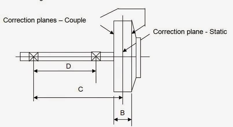
The
following rules and conditions apply to the overhung and narrow rotors.
The
distance between the correction planes is less than 1/3 the distance between
the bearings. ( B < 1/3 D.)
The
permissible dynamic bearing loads are assumed to be equal.
Couple
corrections are made 180 degrees apart in their respective planes.
The
plane for static corrections may be a third plane or either of the planes used
for couple corrections.
Allocate per as static and couple residual unbalance
as follows :
U per Static = U per / 2 * D / 2*C
U per Couple
= U per / 2 * 3*D / 4*C
Permissible
unbalance allocation for overhang and narrow impellers require that two-plane
unbalance correction divided into static and couple unbalance equivalents.
5.3 High Speed Balancing
The
high speed balancing or “ at speed
balancing “ is done for high speed critical centrifugal compressors and
turbines etc. It requires a very sophisticated set up and a balancing machine.
These types of facilities are limited in number worldwide and they are very
expensive as well.
The
installation consists of a chamber capable of holding the rotor along with the
bearing pedestals, and also a place for the balancing personnel to move inside
for weight correction on the same rotor by machining, grinding, etc. The
complete set up is in a bunker and the in an airtight chamber or enclosure. The
chamber is connected to the vacuum pumps. The vacuum is maintained to avoid the
airflow through the impeller. At very high speed the windage and friction will
be very disturbing, and dangerous as well. Secondly it will require a prime
mover of very high horsepower to spin the rotor at that speed. One more problem
will be the heating up of the air inside the chamber. Rotating the rotor in a
vacuum chamber solves all these problems. There are protection devices to
safeguard against the vacuum failure.
Normally a variable speed drive or
motor and gearbox combination is used. The balancing equipment are also very
sophisticated and they include computerised system which calculates the
unbalance and the angular position etc. It records the initial unbalance and also
records all the stepwise corrections. It is worth noting that for balance
correction, say by grinding, the rotor must be stopped and vacuum must be
relieved. Again after the correction, the rotor must be tested in re-evacuated
chamber. This makes the High Speed balancing a very time consuming, labour
intensive and expensive operation.
It
must be noted that all the rotors do not deserve such a stringent testing. The
multistage, critical rotors, falling in the category of “ Flexible Rotors”, meaning operating above
their first lateral (bending) critical speed, must be tested this way. This
testing revels characteristics of the dynamic rotor response.
Please
refer to the following pictures showing a complete set-up for high speed
balancing. Note the enclosure, the bearings with pickups and the vacuum seals,
etc. On these types of machines the critical multi-impeller rotors are also
tested for what is popularly known as “
Over Speed Testing “.

5.4 Field Balancing
This
is one more practical way of balancing the rotating equipment and the name of
this method is due to the fact that it is done in the field. This is
also suitable for big rotors rotating at lower speeds for example air blowers,
fans, etc. Generally this method is used for small finer corrections and not
the major adjusting. This is usually done when the machine vibrations show an
increase and the cause is the imbalance. The rotors such as ID fans show “ out
of balance “ after some use due to thermal distortion, corrosion, erosion, wear
and tear and deposits etc. If the imbalance resulting due to such a problem is
not very high, it can be corrected easily by “ field balancing”. It is much
easier to do a field balancing than, de-coupling, opening the equipment, and
taking out the complete rotor assembly, transporting from site to balancing
facility and then fixing back the same way after the shop balancing.
Secondly,
many of the equipment are so designed that a “ field balancing” provision is
made on the rotor. Electric motors, air fan rotors, and sometimes even the
steam turbines have a provision for adding the balance correction weights without
removing the rotor from the casing. The end covers have widows to get
access to the balance correction ring or slots in which the balance weights are
added and fixed permanently so that they do not move in service.
In
the field balancing, single plane, two-plane and multi plane balancing is
possible. It depends on the shape of the rotor and the running speed. Very
narrow overhung type rotors are balanced in the single plane. Relatively broad
rotor life ID fan rotors and electric motor rotors are balanced in two planes.
Example
of a single plane field balancing, showing measurement points

As
a preparation for the field balancing of the rotor it is essential to verify
that the cause of the vibration is unbalance. After this is confirmed, it is a
god idea to inspect the rotor for any major damage. If the rotor is coated with
dirt and dust or some polymer deposits, it is essential to clean the rotor.
High-pressure hot water cleaning is one of methods to clean at site. Then some
field dimensions like bearing span (D), correction plane and CG ( BL & BR )
, correction radius (R), correction planes and bearings ( A ) etc are required,
to calculate correction weights.
Example of a two - plane field balancing,
showing measurement points

The field balancing is done by using many different equipment. There are some
portable field balancing equipment available. They have portable vibration
pickups and strobe light. The vibration measure provides an indication of the
unbalance mass and the reading is in proportion of the unbalance.
The vibration
magnitude indicated by the equipment may be displacement, velocity or
acceleration depending on the type of transducer and the selected unit of
display.
As
indicated in the two previous examples, the pickup is mounted on the bearing
housing to measure the vibrations. The angle of unbalance can be found out if
there is a shaft “ key “
which is used to trigger the strobe. Other wise optical pickup is also
used to determine the angle.
Second
possible way is to use the “three trial runs “ method. The first run is take in
the rotor in “ as it is “ condition. The vibration amplitude and the phase are
measured. In the second trial a “ suitable trial weight” is attached to the
rotor and the rotor is brought to the operating speed again.
This time the
vibration amplitude and the angle is noted. Then based on these two readings,
the exact balance correction weight is found out and attached. The third run is
usually is a final run and it is expected that the rotor is balanced at this
stage. The vibration levels are within the permissible level. Occasionally a last
“ trim balancing “ is carried out if necessary.
6 BALANCING STANDARDS.
There are many
standards available today, which give guidelines for balancing. One can easily
determine the allowable limits from these standards. One of the most commonly used standard is ISO-1940. This gives the values of Balance Quality
Requirements of the Rigid Rotors.
To use this
standard one must know what type of
rotor is to be balanced. See the Table 1
for determination of the type of rotor. From this table the second thing to
note is the grade. For example
centrifugal pump impellers, and flywheels fall under G 6.3 grade. The steam and gas turbine rotors
and turbo compressor impellers are under grade G 2.5. After selecting the grade
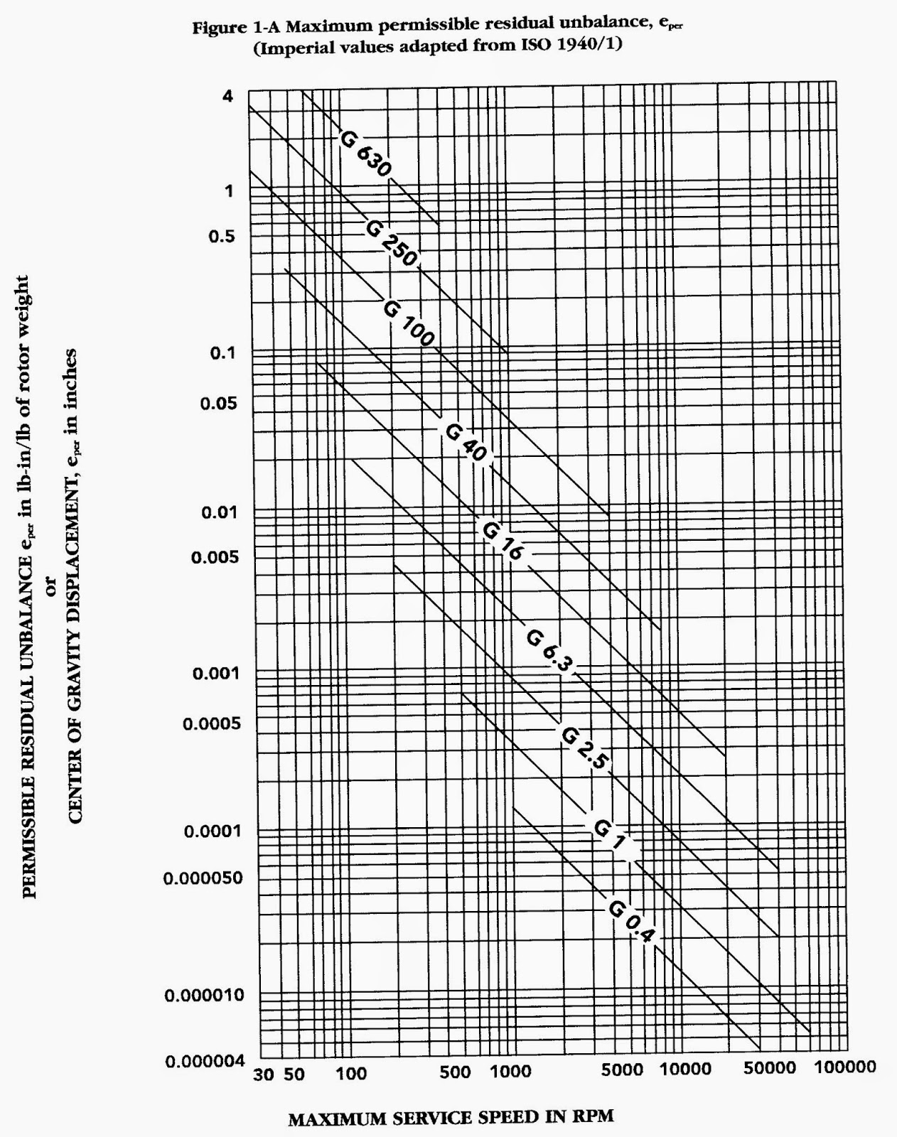
from table 1, next step is to go to Figure
1-A or Figure 1 – B, to find the
maximum permissible residual unbalance e per .
As an example, we
have a centrifugal compressor rotor of weight 2200 lb. weight. The maximum
operating speed is 5000 RPM. The grade
as per table 1 is G2.5. Then the formula become
U per = ( G * e per * weight of rotor / 2 ) Max cont. RPM
= ( 2.5 * 6.0 * 2200 / 2 ) / 5000
= 3.3
oz-inch
If we use the
formula given in API - 617, the
formula is
U per = 4 W / N ,
where W = total rotor weight in lbs. and
N = Max Continuous operation
RPM. Applying this formula to the
previous example, we get
U per = 4 W / N = 4 *
2200 / 5000 = 1.76 oz – inch.
Obviously API - 617 standard is more stringent,
as it allows a smaller permissible unbalance of 1.76 oz-inch compared to the 3.3
oz-inch allowed by ISO -1940.
The other API standards also specify the
similar things as far as dynamic balancing of the rotors is concerned. The
allowable residual unbalance per plane as specified by different API standards
is tabulated as follows-
|
S.N.
|
API STD .
|
APPLICABLE FOR
|
FORMULA
|
|
1
|
API 611
|
Gen. Purpose
Steam Turbines
|
U max = 4 W / N
|
|
2
|
API 616
|
Gas Turbines
For Refineries
|
U max = 4 W / N
|
|
3
|
API 6 17
|
Centrifugal Compressors
|
U max = 4 W / N
|
|
4
|
API 610
|
Centrifugal
Pumps for Petroleum , gas etc
|
U max = 4 W / N
|
Where Umax = residual unbalance in
ounce-inches ( gram-millimetres in SI )
W = Journal static
weight load in pounds ( kilograms in SI )
N =
maximum continuous speed in revolutions per minute RPM.
The above formula
for SI units is expressed as , U max = 6350 W / N
TABLE 1 : BALANCE
QUALITY GRADES & THE ROTOR TYPES ,
ISO 1940
|
Balance Quality
Grade
|
Product of
E per * W
|
ROTOR TYPES –
GENERAL EXAMPLES
|
|
G 4000
|
4000
|
Crankshafts/
drives of rigidly mounted slow ( where the piston speed is less than 9 m/s )
marine diesels with uneven number of cylinders.
|
|
G 1600
|
1600
|
Crankshafts/
drives of rigidly mounted two-cycle
engines.
|
|
G 630
|
630
|
Crankshafts/
drives of rigidly mounted large four-cycle engines and Crankshafts/ drives of
elastically mounted marine diesel engines.
|
|
G 250
|
250
|
Crankshafts/
drives of rigidly mounted fast( where
the piston speed is more than 9 m/s ) four cycle diesel engines
|
|
G 100
|
100
|
Crankshafts/
drives of fast diesel engines with six or more cylinders. And complete
engines for cars, trucks, etc
|
|
G 40
|
40
|
Car wheels,
wheel rims, wheel sets, drive shafts,
Crankshafts/
drives of elastically mounted fast four-cycle engines with six or more
cylinders.
Crankshafts/
drives of engines of cars, trucks, etc
|
|
G 16
|
16
|
Drive shafts (
propeller shafts, cordon shafts with special requirements ) ,
Parts of
crushing machines, agricultural machinery, individual components of engines
for cars, trucks, etc.
|
|
G 6.3
|
6.3
|
Parts of the
process plant machines Centrifuge drums, paper machinery rolls, print rolls,
fans, flywheels, assembled aircraft
gas turbine rotors, , pump impellers, machine tool and general machinery
parts, medium and large electric armatures, small electric armatures
|
|
G 2.5
|
2.5
|
Gas and steam
turbines, rigid turbo generator rotors, turbo compressors, machine tool
drives, medium and large electric armatures with special requirements,
turbine driven pumps
|
|
G 1
|
1
|
Tape recorder
and phonograph drives, grinding machine drives
Small electric
armatures with special requirements
|
|
G 0.4
|
0.4
|
Spindles, discs
and armatures of precision grinders,
Gyroscopes
|
Note : W = 2
p N / 60 rad / sec.

SUMMARY
ON API STANDARDS FOR BALANCING ASPECT
: -
API 617 For Centrifugal Compressors
specifies the following guidelines.
Ref. Para 2.9.5.1: - Major parts of the rotating
element, such as shaft, balancing drum, and impellers shall be dynamically
balanced. When a bare shaft with a single keyway is dynamically balanced, the
keyway shall be filled with a fully crowned half-key. The initial balance
correction to the shaft shall be recorded. A shaft with keys 180 degrees apart
but not in the same transverse plane shall also be treated as described above.
Ref.
para 2.9.4.3: - The rotating element shall be multiplane dynamically balanced
during the assembly. His shall be accomplished after adding no more than two
major components. Balancing correction shall be applied only to the elements
that are added. Other components may require minor corrections during the final
trim balancing of the completely assembled element. On rotors that have single
keyways, the keyway shall be filled with fully crowned half-key. When
specified, the weight of all half keys used during the final balancing of the
assembled element shall be recorded on the residual unbalance worksheet. The
maximum allowable residual unbalance per plane ( journal ) shall be calculated
as follows; -
U max
= 4 * W / N ( and
in SI units U max = 6350 W / N )
Where Umax = residual unbalance in
ounce-inches ( gram-millimetres in SI )
W
= Journal static weight load in pounds ( kilograms in SI )
N
= maximum continuous speed in revolutions per minute RPM.
When spare rotors are supplied they shall be
dynamically balanced to the same tolerance as main rotor.
Ref.
Para 2.9.5.4 – High speed balancing ( balancing in the high speed balancing machine at the
operating sped ) shall be done only with the purchaser’s specific approval. The
acceptance criteria for this balancing shall be mutually agreed upon by the
purchaser and the vendor.
The other standards like API : 610-for pumps,
API :611 – for steam turbines, API : 672
– packaged integrally geared compressors, etc also provide similar guidelines.
7 References
ISO 1940 –
Balance Quality Of Rotating Rigid Bodies – classifies all rigid rotors and
recommends balance tolerances for them.
API STANDARD 610 - Centrifugal Pumps For Petroleum , Heavy Duty
Chemical, And Gas Industry.
API STANDARD 611- General Purpose Steam Turbines
For Refinery Services.
API STANDARD 616 – Gas Turbines for Refinery
Services.
API STANDARD 617 - Centrifugal Compressors For Petroleum , Chemical, and Gas Service
Industry.
Machinery
Component Maintenance and Repair by Heinz P Bloach & Fried K. Geitner –
Gulf Publishing.
Compressors
Selection & Sizing –By Royce N. Brown – Gulf Publishing Company.
Hard – Bearing
Balancing Machines – SHENCK RoTec GmbH.
PGW- Turbo
Compressors for the Process Industry – Pumpen- und Geblasewerk Leipzig GmbH.
2 comments:
“As a military family, we are very thankful for Mr Lee professional service. he was attentive, knowledgeable and took his time to walk us through the loan process. We were informed in a timely manner of any pertinent details we needed to take into account. He was very approachable, understanding and trustworthy. We can’t thank him enough for his excellent service. We highly recommend his and feel blessed to have had his loan assistance to enable us have our home purchase. Military and non military families, Mr Lee you would want to work with for your home purchase & any kind of loan asistance!”
Mr Lee Loan Officer Contact Details:WhatsApp : + 1-989-394-3740E-Mail: lfdsloans@outlook.com
Great tips regrading shrink machine . You provided the best information which helps us a lot. Thanks for sharing the wonderful information.
Post a Comment